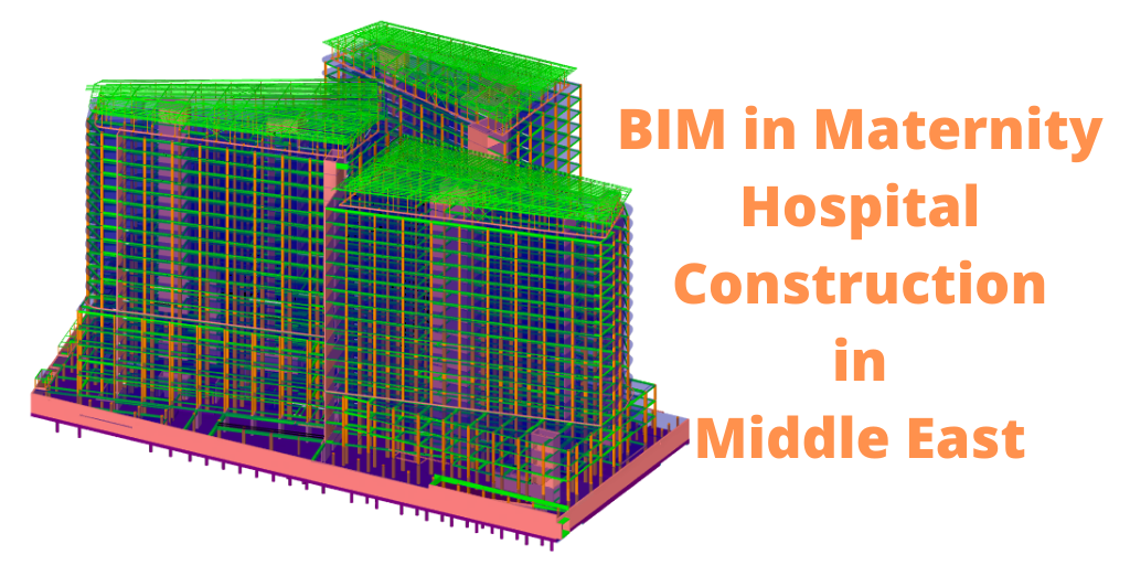
How BIM is being used in a maternity hospital construction in Middle East?
Project
Design, Build, Furnishing, Medical Equipment and Operational Maintenance of the New Maternity Hospital in Middle East
Summary
Building Information Modeling (BIM) continues to evolve and grow along with their respective application in practice. One of the key advantages of BIM is that is facilitates the development of detailed information and analysis much earlier in the building process to improve decision making and reduce downstream changes. The increases in cost of construction and combined complexity inherent in healthcare construction projects provides an opportunity to harness the strengths of BIM and provide much more detailed information early in the development of a healthcare construction project.
Healthcare related project which implemented BIM in the programming phase is presented in this case study. Benefits to stakeholders includes
- visualization,
- time saved relative to concept updates, and
- instant quantity take-offs within few clicks.
Total Building Floors – 2 Basements, G+18 Floors of Area equals to 9000 square meters
BIM Model development in different software were as follows:
- BIM Structure Modeling in Autodesk Revit 2018
- BIM Architecture Modeling in Autodesk Revit 2018
- BIM MEP Modeling Autodesk Revit 2018
- Clash Coordination & Clash Detection Navisworks Manage 2018
- Clash Report Navisworks Manage 2018
- 2D Shop Drawing Autodesk Revit & AutoCAD 2018
- Document-Excel, Word and Powerpoint
Input data from Client
- Architecture design drawings
- Structure design drawings
- HVAC (Heating, Ventilation and Air Conditioning) design drawings
- Plumbing design drawings
- Electrical design drawings
- Medical Gas design drawings
- Pneumatic design drawings
The Input design data received as in LOD 200 CAD drawings format.
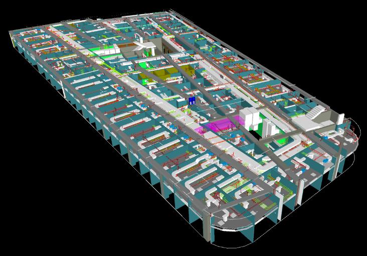
Building Information Modeling – BIM (Creating LOD 300 BIM Models)
The next step was to convert these 2D design drawings into the 3D BIM models using Autodesk Revit software. Further classified as:
- HVAC
- Supply Air Duct System
- Return Air Duct System
- Exhaust Air Duct System
- Smoke Make up / Exhaust Air System
- Chilled Water Supply / Return System
- Hot Water Supply / Return System
[su_image_carousel source=”media: 1986,1985,1984,1978,1982″ slides_style=”minimal” controls_style=”light” crop=”none” align=”center” captions=”yes” autoplay=”3″]
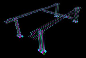
- PLUMBING
- Drainage System
- Water Supply
- Fire Fighting
[su_image_carousel source=”media: 1987,1979,1981″ slides_style=”minimal” controls_style=”light” crop=”none” align=”center” captions=”yes” autoplay=”3″]
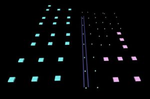
- ELECTRICAL
- Emergency & Exit System
- Lighting
- Fire Alarm
- Passive System
- Security System
- Power Distribution
- MEDICAL GAS
- PNEUMATIC System
BIM Coordination (Upgrading to LOD 350 BIM Models)
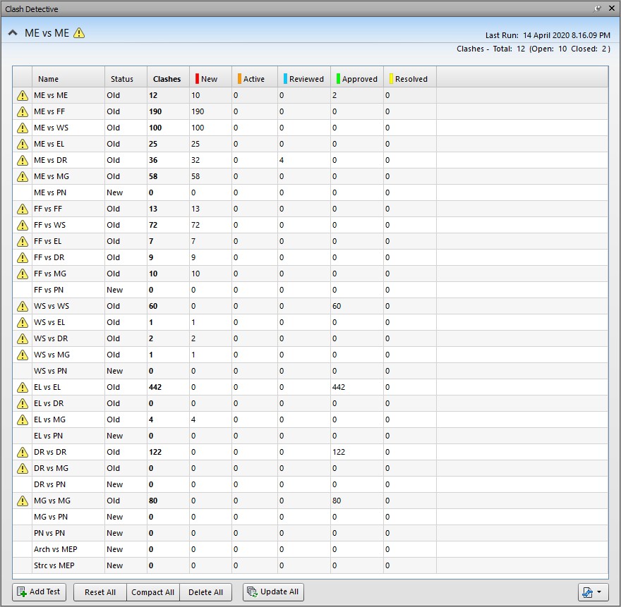
The next step after completing the modeling part as per the design drawing is to check the clashes within the MEP services as well as with Architecture & Structure to make & deliver the clash free model. This step is carried out by using the Navisworks software, in that all the input data is used as NWC files which is exported from Revit.
By combining / appending all the NWC’s created the NWF file with all the clash tests in batches within the MEP services and with the Architecture & Structure.
This is most important part of construction stage, to ensure that before construction the entire elements/Items are clash free.
Following process was followed during BIM Clash coordination stage
- Using Clash report from model to identify the major clash and minor clash.
- Solve the clashes based on specific criteria and update the model accordingly. (Note that solving clashes requires deep domain expertise of MEP services. Simply a rerouting does not works and can hamper the technical feasibility of MEP systems. Therefore, it is very important to have a deep domain expertise as how to resolve MEP clashes and maintain the technical design integrity)
- Prepare Clash free model to generate shop drawings.
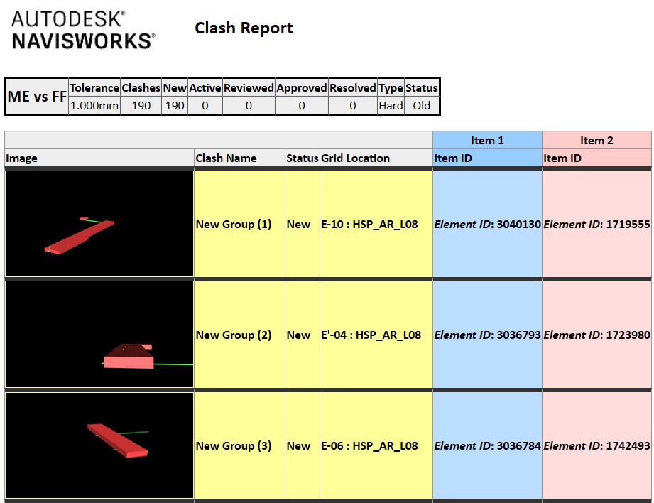
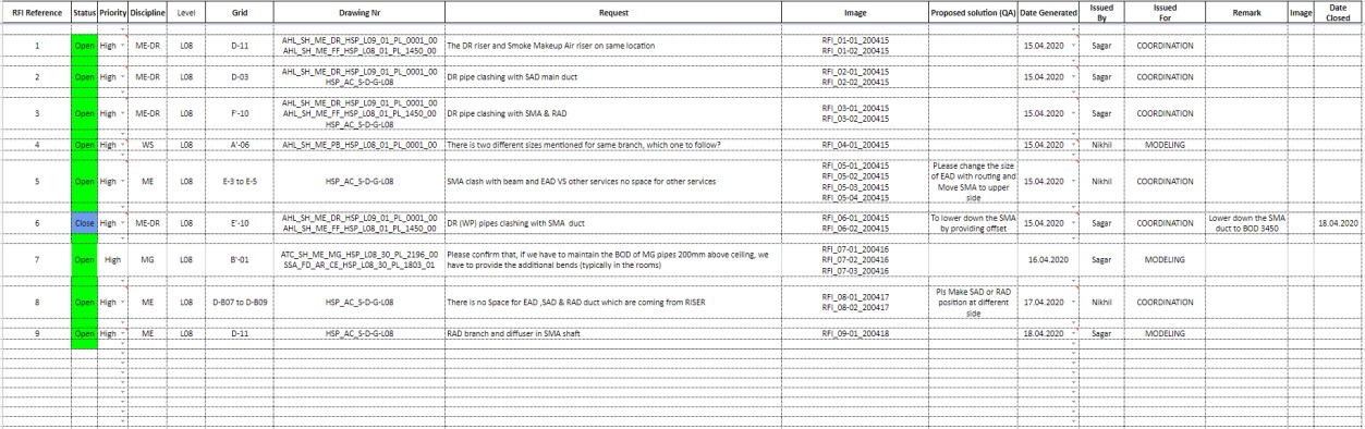
After identifying the major clashes, we raised the RFIs to client consultants to resolve the critical issues by changing the design routing of MEP services or changes as per site conditions.
BIM Documentation (Upgrading to LOD 400 BIM Models)
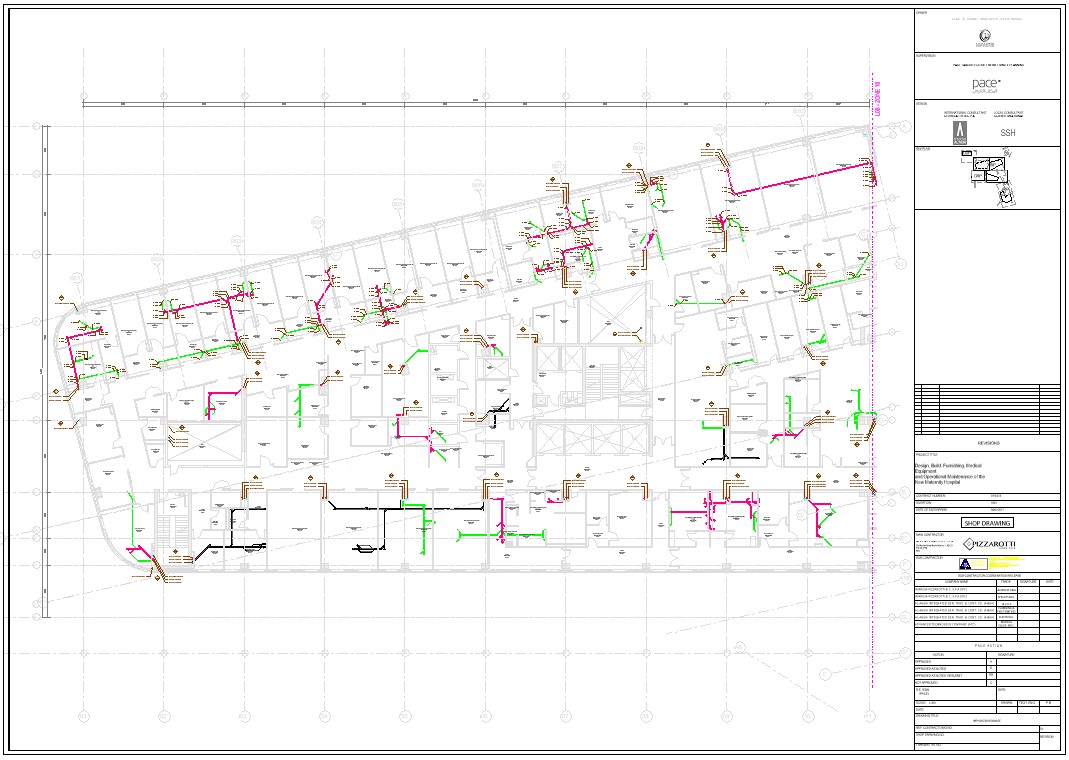
Creating and exporting Shop Drawings from BIM models
The coordinated drawings for the MEPF services are generated from the Revit by exporting the files for 2D information, which will be use as shop drawing input for construction. The coordinated drawing contains the size, dimensions and level of services with the necessary coordinate’s grids for installation.
Shop drawing for this project is segregated in following types
- Combined Services Drawings or CSDs – Contains all the services merged and the information provided.
- Sections – Provides sections at the critical locations such as corridors, electrical/mechanical rooms for better understanding and to help the installation.
- Discipline Specific Drawings – Generated as per services for different sub-contractors like Mechanical, Piping, Electrical contractor for installation.
Conclusion
Context & Objectives
OneClick BIM coordinated with the client consultants, on-site engineers, construction managers and construction team, for the requirement of a project and produced the well coordinated and qualitative clash free MEP shop drawings from BIM models which were later upgraded to As-Built MEP drawings.
Realisations
- Preparation of shop drawing from LOD 200 design drawings of all MEP services i.e. Ducting, Chilled & Hot Water Piping, Drainage, Water Supply, Medical Gas, Pneumatic Tubes, Passive and Security Cable Trays, Firefighting, Fire Alarm & Lighting.
- Preparation of New Family as Per the Project Requirements.
- Preparation of Clash Report by Using Navisworks software.
- Coordination of MEP services.
- Preparation of As Build Drawing using Site Red Line Mark up.
- Preparation of Schedule of Duct, Cable Tray, Pipe lengths Quantity of Fittings, Lighting.
Results
- Closely BIM coordination with the other subsystems, gives the highest standard ensuring a better and accurate model as per the client requirement.
- Coordinate with Onsite Engineers and BIM Team for the detailed design and layout.
- Providing a standard template and standard filters for easier usage for the clients use.
- Mostly done and for better understanding of the site conditions.
We at OneClick BIM has helped dozens of companies since 2015 in visualizing their BIM / VDC processes utilizing BIM models in regions such as Singapore, UAE, US, UK, Australia, New Zealand, Malaysia, India, and many more. If you are looking for having support in your BIM processes and or BIM manpower requirements, we will listen to your needs and provide you with end to end BIM Solutions. We are there for you to support in your BIM journey.